Question: Fundamental Problem 1.1 4 of 20 Review Consider the beam in the figure below. Take P = 24kN kN Vc 20 (Figure 1) Previous Answers Request Answer Submit Figure 1 of 1 Incorrect; Try Again; 2 attempts remaining Part C 60 kN-m Determine the internal bending monment at point C in the beam.
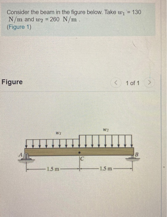
Solved Consider the beam in the figure below. Take w1 = 130 | Chegg.com
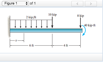
Figure 9.2: Bifurcation of equilibrium in a compressed cantilever beam Consider a cantilever beam of length L made of a material with Young’s modulus E and whose uniform cross section has a moment of inertia with respect to the x 2 axis I22. The beam is subjected to a compressive load P , as shown in the gure.

Source Image: quizlet.com
Download Image
Plots of V(x) and M(x) are known as shear and bending moment diagrams, and it is necessary to obtain them before the stresses can be determined. For the end-loaded cantilever, the diagrams shown in Figure 3 are obvious from Eqns. 4.1.1 and 4.1.2. Figure 4: Wall reactions for the cantilevered beam.
Source Image: chegg.com
Download Image
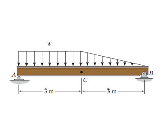
Solved Consider the beam shown in (Figure 1). Solve this | Chegg.com 1 . Draw the shear… Question: Consider a beam shown in the figure below. Let P = 90kN P = 90 k N and w= 4kN m−1 w = 4 k N m − 1. Draw the shear force and bending moment diagram of the
Source Image: chegg.com
Download Image
Consider A Beam Shown In The Figure Below.
1 . Draw the shear… Question: Consider a beam shown in the figure below. Let P = 90kN P = 90 k N and w= 4kN m−1 w = 4 k N m − 1. Draw the shear force and bending moment diagram of the Consider the cross-section of a beam shown in the figure below. Assume the beam is experiencing an internal shear force of 5,000 N. Using this information, calculate the magnitude of the bending shear; Consider the object shown in figure. Suppose that P=6.5 kN. Determine the magnitudes of the internal normal force and internal shear force at
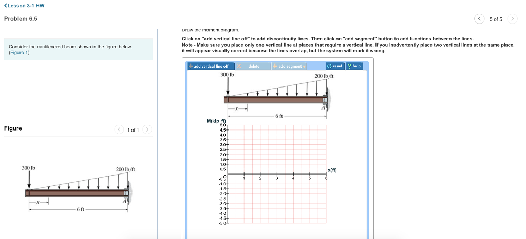
Solved Consider the cantilevered beam shown in the figure | Chegg.com
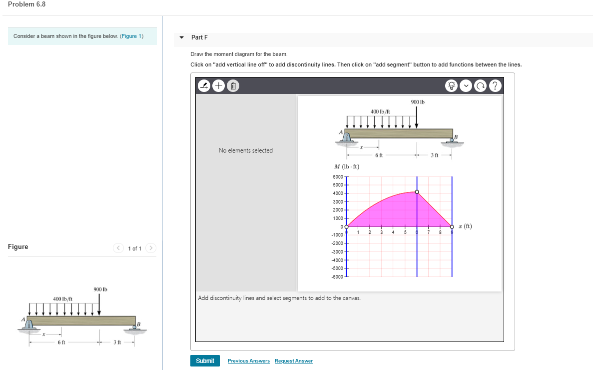
Answer Unlock Previous question Next question Transcribed image text: Consider the beam shown in (Figure 1). Solve this problem using the basic method. Assume A is a pin and B is a roller. Assume that the support at B provides reaction forces that are directed either outward or toward the supporting surface perpendicular to the surface. Solved Problem 6.8 Consider a beam shown in the figure | Chegg.com
Source Image: chegg.com
Download Image
Solved Consider the beam in the figure below. Take | Chegg.com Answer Unlock Previous question Next question Transcribed image text: Consider the beam shown in (Figure 1). Solve this problem using the basic method. Assume A is a pin and B is a roller. Assume that the support at B provides reaction forces that are directed either outward or toward the supporting surface perpendicular to the surface.
Source Image: chegg.com
Download Image
Solved Consider the beam in the figure below. Take w1 = 130 | Chegg.com Question: Fundamental Problem 1.1 4 of 20 Review Consider the beam in the figure below. Take P = 24kN kN Vc 20 (Figure 1) Previous Answers Request Answer Submit Figure 1 of 1 Incorrect; Try Again; 2 attempts remaining Part C 60 kN-m Determine the internal bending monment at point C in the beam.
Source Image: chegg.com
Download Image
Solved Consider the beam shown in (Figure 1). Solve this | Chegg.com Plots of V(x) and M(x) are known as shear and bending moment diagrams, and it is necessary to obtain them before the stresses can be determined. For the end-loaded cantilever, the diagrams shown in Figure 3 are obvious from Eqns. 4.1.1 and 4.1.2. Figure 4: Wall reactions for the cantilevered beam.
Source Image: chegg.com
Download Image
DARPA looks to laser to beam power across the world Answer and Explanation: 1 Become a Study.com member to unlock this answer! Create your account View this answer The FBD of the beam is shown below. Support at A is a pin so it has reactions

Source Image: newatlas.com
Download Image
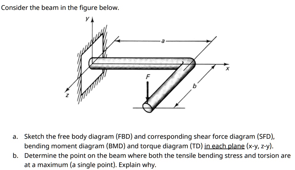
SOLVED: Consider the beam in the figure below a. Sketch the free body diagram (FBD) and corresponding shear force diagram (SFD) bending moment diagram (BMD) and torque diagram (TD) in each plane ( 1 . Draw the shear… Question: Consider a beam shown in the figure below. Let P = 90kN P = 90 k N and w= 4kN m−1 w = 4 k N m − 1. Draw the shear force and bending moment diagram of the
Source Image: numerade.com
Download Image
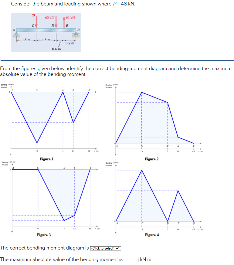
Solved Consider the beam and loading shown where P = 48 | Chegg.com Consider the cross-section of a beam shown in the figure below. Assume the beam is experiencing an internal shear force of 5,000 N. Using this information, calculate the magnitude of the bending shear; Consider the object shown in figure. Suppose that P=6.5 kN. Determine the magnitudes of the internal normal force and internal shear force at
Source Image: chegg.com
Download Image
Solved Consider the beam in the figure below. Take | Chegg.com
Solved Consider the beam and loading shown where P = 48 | Chegg.com Figure 9.2: Bifurcation of equilibrium in a compressed cantilever beam Consider a cantilever beam of length L made of a material with Young’s modulus E and whose uniform cross section has a moment of inertia with respect to the x 2 axis I22. The beam is subjected to a compressive load P , as shown in the gure.
Solved Consider the beam shown in (Figure 1). Solve this | Chegg.com SOLVED: Consider the beam in the figure below a. Sketch the free body diagram (FBD) and corresponding shear force diagram (SFD) bending moment diagram (BMD) and torque diagram (TD) in each plane ( Answer and Explanation: 1 Become a Study.com member to unlock this answer! Create your account View this answer The FBD of the beam is shown below. Support at A is a pin so it has reactions
